Испанский
 Россия

Purlins vs Girts for Roll Forming Setup
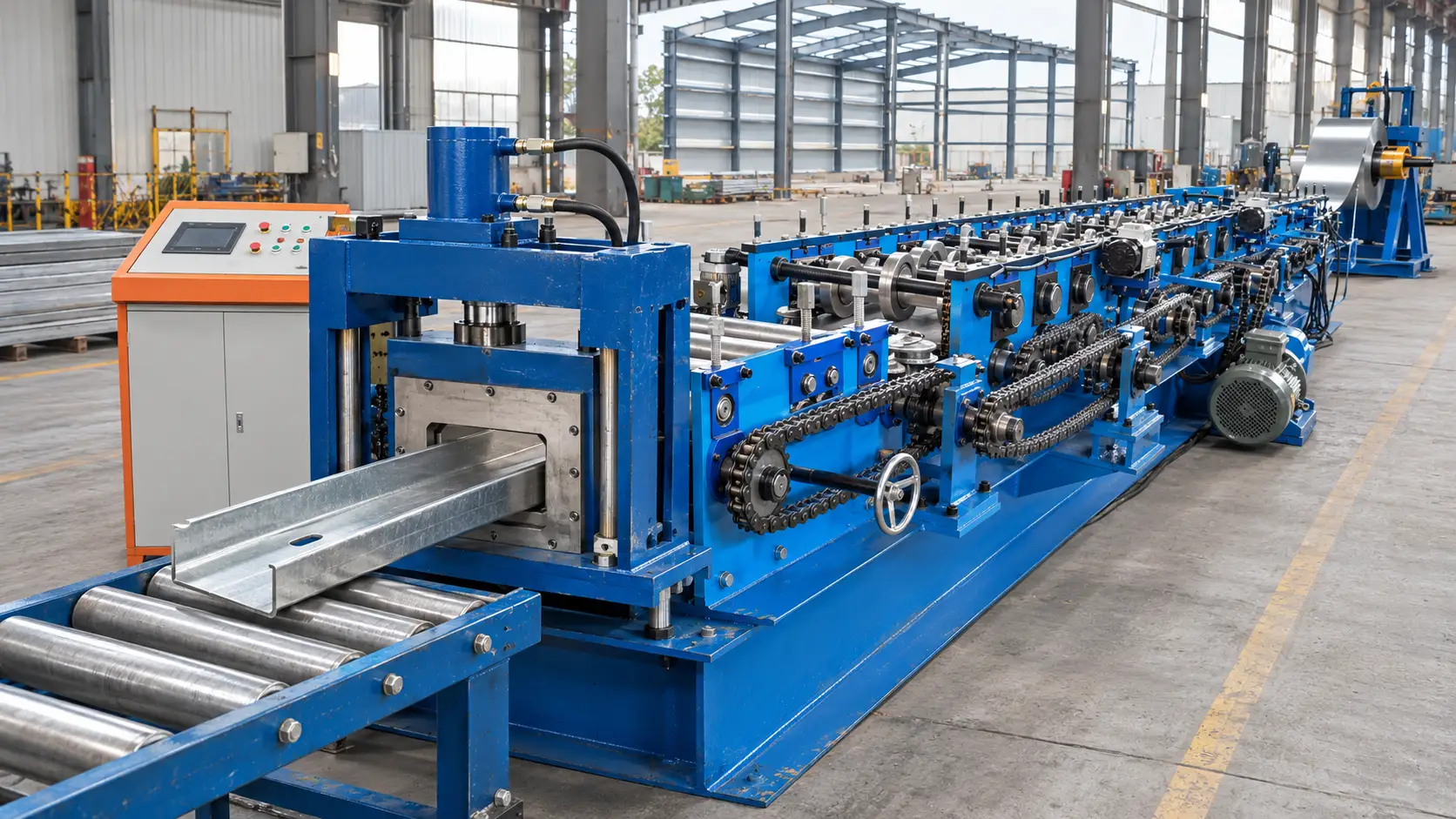
Purlins and girts are both secondary framing members, but they work in different parts of a metal building. Purlins support roof panels between the primary frames. Girts support wall cladding between columns. That location changes the loading direction, connection details, hole pattern, and sometimes the preferred C or Z profile. For a roll forming buyer, the practical question is therefore not only whether a section is called a purlin or a girt. The drawing must show how the finished member will be oriented, connected, punched, and measured.
A general introduction to purlins in metal construction can explain roof support and material choices. This guide focuses on the manufacturing boundary: how purlin and girt requirements become a workable profile drawing, punching program, cut length, and line configuration. Final member size, spacing, thickness, and connection design must still be verified by the project engineer.
The Key Difference Between Purlins and Girts
The simplest distinction is location. A purlin runs along the roof, normally spanning between rafters or rigid frames. A girt runs along the wall, normally spanning between columns and carrying wall cladding. Both may use cold formed C or Z sections, but the same nominal section should not be assumed to use the same holes or installation orientation in both positions.
|
Decision field |
Purlin |
Girt |
|
Building location |
Roof secondary framing |
Wall secondary framing |
|
Supported element |
Roof panel or deck |
Wall panel or cladding |
|
Typical section family |
C or Z section |
C or Z section |
|
Connection drawing |
Rafter, frame, lap, and bridging details |
Column, wall panel, and bridging details |
|
Punching input |
Roof connection and accessory hole coordinates |
Wall connection and cladding hole coordinates |
How C and Z Profiles Fit Each Application
C Sections
A C section has flanges facing the same direction. It is often selected where straightforward end connections and non lapped layouts are appropriate. The open side and lip orientation must be shown on the drawing because they control the roller arrangement, punch side, and receiving orientation. A buyer comparing a C purlin roll forming machine should confirm the web, flange, lip, thickness range, and whether the line must produce one fixed profile or multiple sizes.
Z Sections
A Z section has flanges offset in opposite directions. Z members are frequently specified where the framing design uses overlapping or lapped arrangements, although the actual lap and connection must come from the engineer’s drawing. The machine must reproduce the correct flange direction and hole datum consistently. A dedicated Z purlin roll forming machine can suit a stable profile family, while a flexible line may be more useful when C and Z orders share one production schedule.
How the Profile Drawing Controls the Roll Forming Line
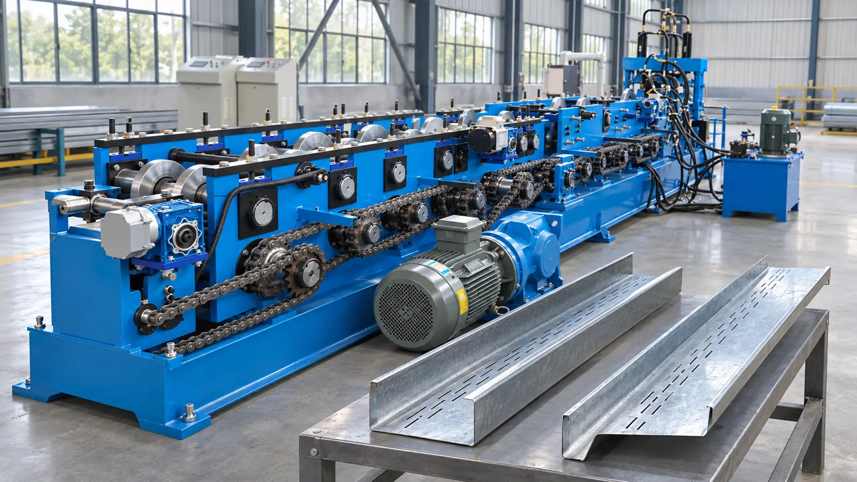
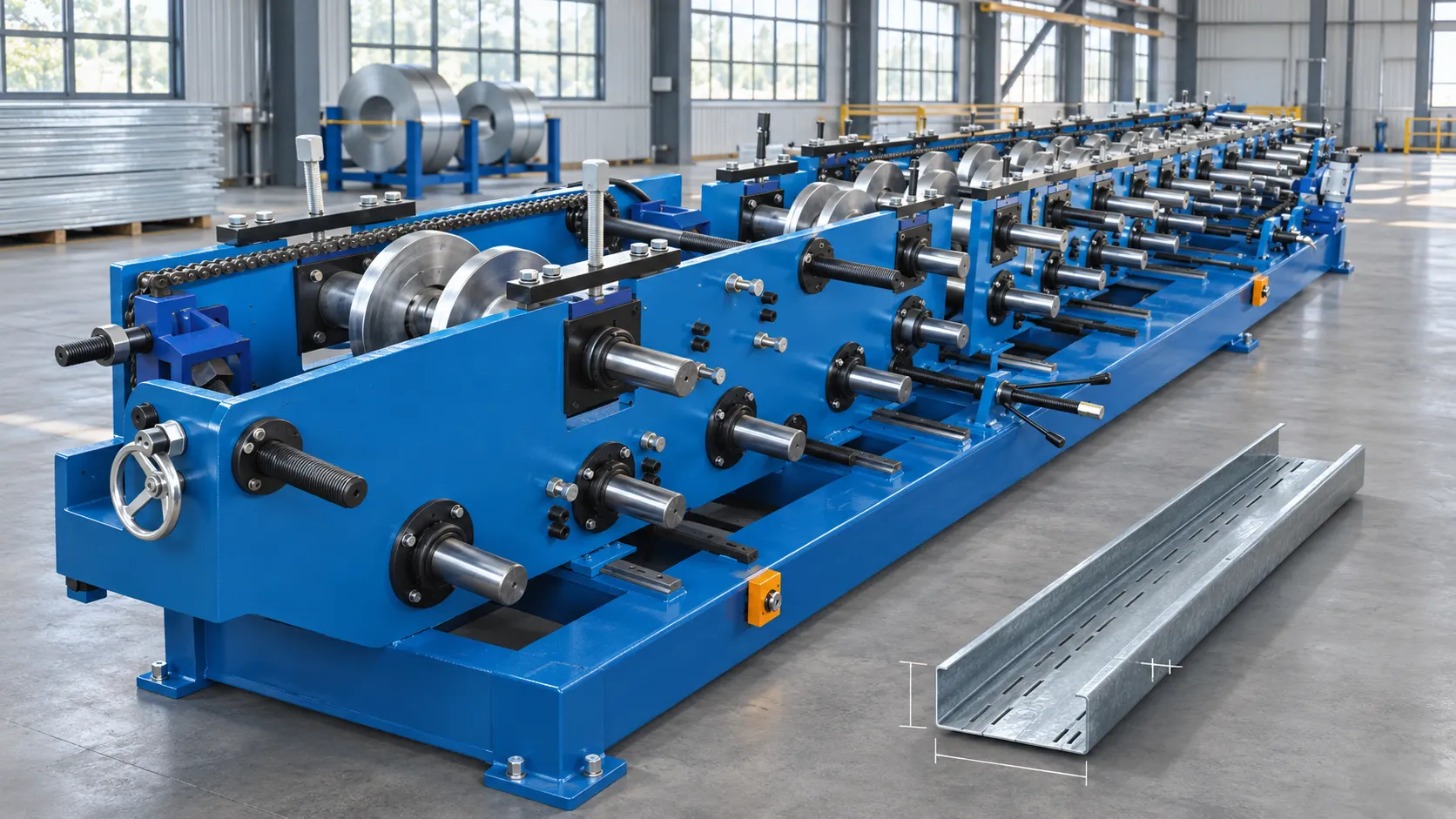
The drawing is the controlling manufacturing document. Xinbo’s automatic interchangeable C/Z purlin roll forming machine is described for producing different C and Z sizes without replacing the forming rollers when the size changes. The published configuration also includes automatic control, punching, and cutting. Those capabilities are useful only when every adjustable dimension and hole coordinate is defined clearly.
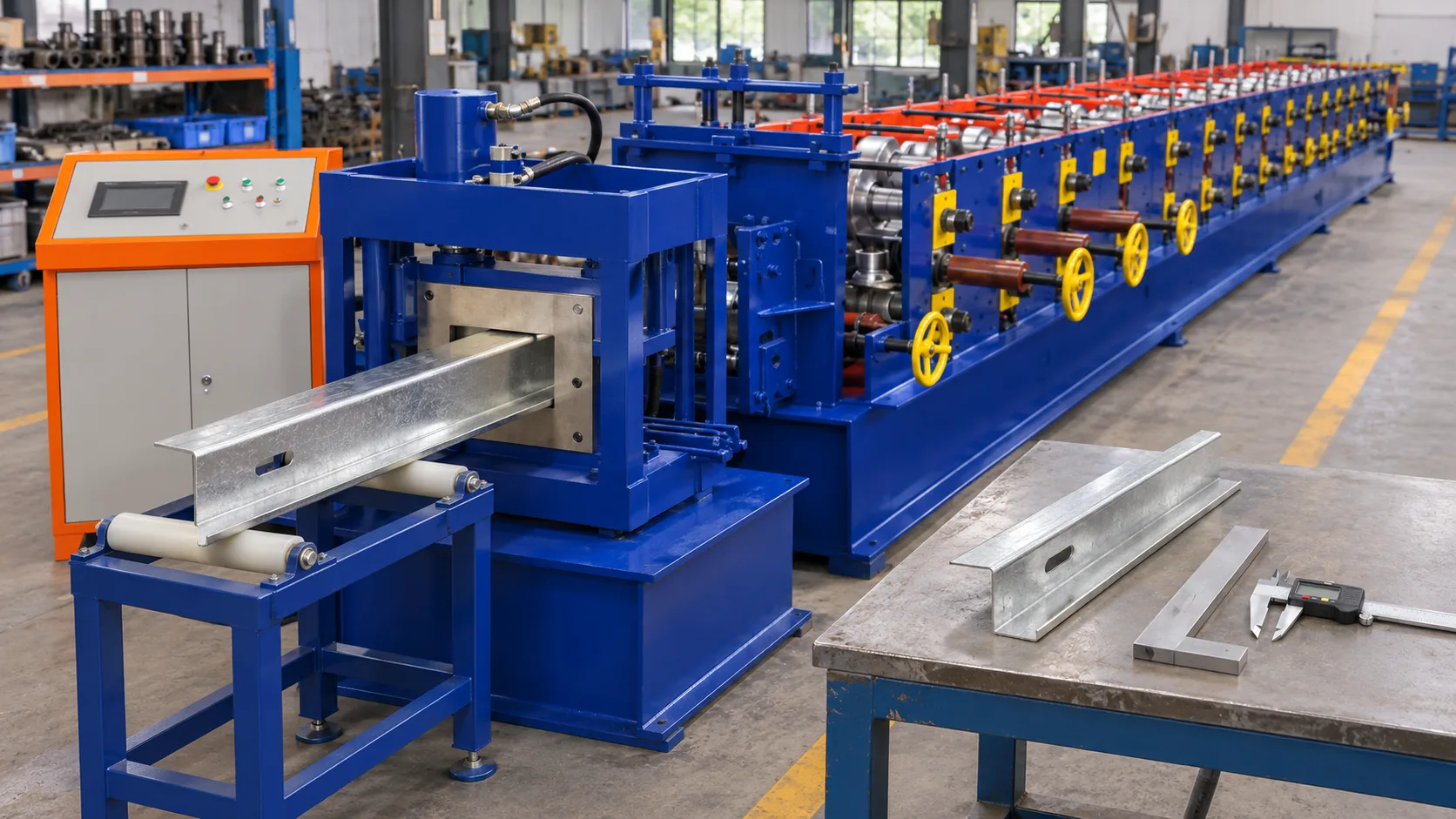
A production drawing should identify the finished web depth, both flange widths, both lip dimensions, inside radius where relevant, material type, yield strength, coating condition, and base metal thickness. It should also state which surface is the reference face and which end is the leading end. If the member is asymmetric, a simple section sketch and an installation view prevent a mirrored profile from being accepted by mistake.
Do not use a generic size name as the only input. Two suppliers may use the same nominal depth while applying different flange, lip, radius, or thickness values. Those differences affect roll tooling, springback, straightness, nesting, and whether a finished girt fits the intended cleat or wall system.
Hole Patterns and Datum Control
Hole offset problems usually begin before the coil reaches the machine. A useful punching drawing defines hole diameter or slot size, longitudinal pitch, edge distance, pattern repetition, and the relationship between holes and the cut end. It must also state whether dimensions are measured from the leading edge, trailing edge, profile centerline, web edge, or another physical datum.
Purlin and girt drawings should not share a punching program merely because their cross sections look alike. Roof members may need frame connection holes, bridging locations, or lap related patterns. Wall members may use different column connections, sag rods, bridging, or panel support details. The exact pattern depends on the building system. Keeping separate program names, revision numbers, and first piece records reduces the risk of loading the right profile with the wrong hole layout.
A Practical Roll Forming Setup Sequence
A controlled setup follows the drawing from coil to finished member. The sequence below is more reliable than adjusting the line only after a completed length fails inspection.
- Verify the coil grade, yield strength, coating, width, and base metal thickness against the job traveler.
- Confirm whether the job is a purlin or girt and check the section orientation before setting the rollers.
- Load the correct size parameters and verify web, flange, and lip settings at a safe trial speed.
- Load the approved punching program and check its datum, pattern direction, and revision number.
- Run a first piece, then measure cross section, twist, bow, hole position, and cut length before continuous production.
- Record the accepted settings so the same part can be reproduced without relying on operator memory.
Xinbo publishes a usual thickness range of 1.5 to 3.0 mm and a production speed range of 0 to 15 m/min for its automatic interchangeable C/Z model, with customization available. These figures describe the listed machine, not a universal rule for every purlin or girt. Actual stable speed depends on the profile, material, punching cycle, cut method, and required tolerance.
What to Include in a Machine Request
Before comparing quotations across the C U Z and Omega purlin machine range, send the same technical package to every supplier. Include profile drawings for every required C and Z size, material grade and yield strength, minimum and maximum thickness, coil width if known, all hole and slot drawings, required cut length tolerance, target output, electrical standard, and the preferred changeover method.
Also state whether punching occurs before or after forming, how finished parts will be supported, and how acceptance will be measured. For mixed purlin and girt production, ask the supplier to demonstrate at least one part from each family during the factory acceptance test. A successful test should verify the drawing, not only that the machine can run coil.
Вывод
Purlins and girts may share C or Z geometry, but they do not share the same job automatically. Roof and wall locations create different connection, orientation, and punching requirements. The safest purchasing approach is to treat the approved profile and hole drawings as the source of truth, then select a line that can reproduce those parts with controlled size change, punching datum, cut length, and inspection records.
Frequently Asked Questions
Can the same roll forming machine make purlins and girts
Yes, when both member families use profiles, thicknesses, materials, and size ranges within the line’s verified capability. Separate punching programs and orientation checks may still be required.
Are girts always C sections
No. Girts may be specified as C or Z sections, depending on the building system and engineering design. The approved drawing determines the correct profile.
Should hole locations be measured from the cut end
Only when the drawing defines that datum. Some programs reference the leading edge, profile centerline, or another feature. The machine program and inspection method must use the same reference.
What information is most important for a quotation
Provide the profile drawing, material grade, yield strength, thickness range, hole pattern, required speed, cut tolerance, changeover expectation, and electrical standard.
For a fit check, request a profile and punching review from Xinbo and provide both the purlin and girt drawings, including every required size and hole pattern.
Связанные посты

Хорошее качество
XinBo машина, делающая CO. LTD является профессиональным производителем и экспортером в машине для формирования рулона,
ПРОСМЕТЬ БОЛЬШЕ→


 Russian
 English
 Spanish
 Portuguese
 Arabic
 French
 Dutch
 Turkish
 Swahili
 Serbian
 Romanian