الإسبانية
 روسيا

C/Z Purlin Roll Forming Defects: How to Fix Twist, Bow, Flare, Hole Offset and Cut-Length Errors
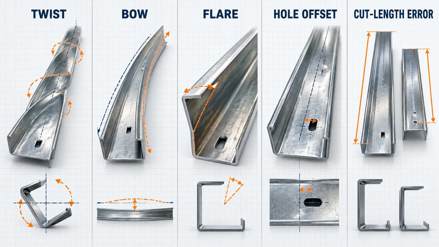
C/Z purlin defects are easier to correct when the symptom is classified before any roll is moved. Twist, bow, end flare, hole offset and cut-length error can share upstream causes—material variation, poor entry alignment or an incorrect recipe—but they do not use the same adjustment. Changing several stations at once removes the evidence and can create a second defect.
Use this as a fault-isolation guide for trained personnel. Stop the line and follow the machine manual and plant lockout/tagout procedure before entering the tooling area. Record original settings so every trial can be reversed.
Use One Inspection Order for All Five Defects
Start with the same sequence regardless of the visible symptom. It separates material, setup, forming, punching and cutting causes before fine adjustment:
- Confirm the job. Match the loaded coil, grade, yield strength, thickness and width to the approved drawing and PLC recipe. Check the coil for edge wave, camber, dents or telescoping.
- Measure the free part. Place a sample on a flat inspection surface. Conveyors, stacking arms or a tight bundle can temporarily force a misleading shape.
- Find where the error begins. Run a short strip slowly and inspect it after the guide, leveler and selected forming stations where safe sampling is designed into the line.
- Check symmetry and condition. Verify guide centering, roll gaps, shaft alignment, fasteners, bearings, tooling cleanliness and changeover positions before using correction rolls.
- Then verify punch and cut references. Confirm encoder contact, datum selection, tool position, cut delay and recipe compensation with a steel tape and several consecutive parts.
The exact checks depend on the installed components. The C, U, Z and Omega purlin machine range includes different line arrangements, so technicians should use the electrical, hydraulic and tooling drawings for the purchased machine.
Twist: The Profile Rotates Along Its Length
A twisted purlin will not sit flat when one end is held level. First determine whether rotation is steady, becomes worse along the part, or appears after a size change. Common causes include off-center strip entry, unequal left/right roll gaps, a changeover position that is not symmetrical, loose tooling, worn bearings, coil camber or unequal residual stress from the material.
Center the strip through the entry guide and confirm the leveler is not steering it. Compare matching roll positions from side to side where twist first appears. Repair mechanical looseness before compensation. Make small, documented corrections and run several parts after each change. Do not use the final stand to hide an earlier twist; that often trades rotation for bow or dimensional error.
Bow: The Purlin Curves Instead of Remaining Straight
Identify the direction first. Side bow, sometimes called camber, is curvature in plan view; vertical bow is curvature when viewed from the side. Check the incoming coil edge, leveler setting and exit support. If the defect exists before the cutoff, focus on material tracking and the forming stands. If it appears only after cutting or unloading, examine residual stress, blade support and handling.
Verify that the conveyor is not lifting or dragging the section. Check top-to-bottom roll gaps and unequal elongation between the web, flanges and lips. Correct the earliest abnormal station, then use a straightening unit only for the small remaining error. Excessive counter-bend may fail when length, thickness or grade changes.
Flare: The Flange or Lip Opens at the Cut End
Flare is an outward opening near one or both ends while the middle of the part may measure correctly. It often points to stored forming stress released by cutting, insufficient closure in the final passes, poor cutoff support, excessive blade clearance or a blade that deforms the section. Compare dimensions at mid-length and at both ends before moving rolls.
Inspect the cutoff for burr, crush marks and asymmetric contact. Confirm the profile is fully supported during the cut. If the end is clean but opens after release, apply a small, balanced closure correction in the final forming stages and recheck twist. If the blade is pushing the flange, service or realign the cutting die first; roll adjustment cannot reliably compensate for a distorted cut.
Hole Offset: Classify Constant, Cumulative or Random Error
Measure each hole center from the same drawing datum. A constant offset usually indicates the wrong recipe datum, punch-tool position or programmed compensation. An error that grows along the part suggests encoder scale error, measuring-wheel slip or material movement. Random error points more often to intermittent slip, a loose sensor, unstable strip entry or inconsistent stopping and clamping.
Check the punch tool and reference sensor before editing the recipe. Clean the measuring wheel, confirm contact and compare indicated travel with an independent measurement. Correct only the matching parameter: zero offset for constant error, scale calibration for cumulative error, or grip/sensor stability for random error. Recheck hole pitch and the first-hole datum.
Cut-Length Error: Diagnose the Pattern Before Compensation
Use at least five consecutive parts. If every part is long or short by nearly the same amount, verify blade position, cut delay and fixed compensation. If the error grows with length, calibrate encoder scale and inspect wheel diameter or slip. If lengths scatter, look for unstable feeding, encoder vibration, loose couplings, servo timing, hydraulic response or material movement during the cut.
For a stop-to-cut line, confirm the strip reaches a stable stop before the blade enters and that clamping does not pull the profile. For flying cutoff, verify synchronization between line speed and the moving carriage. Calibrate at the actual production speed and thickness; a correction derived from slow manual jogging may not represent dynamic operation.
How Xinbo’s Configuration Changes the Fault Tree
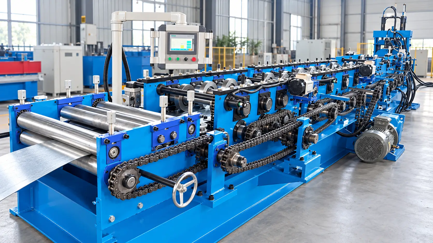
Xinbo’s published automatic interchangeable C/Z purlin line lists a guide, leveler, hydraulic hole punching, forming unit, hydraulic cutting, electrical control and hydraulic system. Its CZ purlin cold roll forming machine page also describes PLC dimension adjustment, servo-driven switching, hydraulic or servo punching and flying cutting. That component flow determines where to isolate an error and which recipe, encoder, hydraulic or mechanical checks are relevant. Confirm the exact as-built line before applying any setting change.
Verify the Repair Before Returning to Production
After each adjustment, produce a small batch using the same coil, recipe, speed and support. Measure profile dimensions, twist or bow over a defined gauge length, first-hole datum, hole pitch and cut length. Record the setting and result. Then repeat at the affected minimum and maximum thickness or size; a correction at one end of the range can move another size out of tolerance.
If the defect returns after a new coil, size change or speed increase, treat that event as evidence. It may indicate material-driven springback, an incomplete automatic positioning cycle or a dynamic feed/cut problem rather than a permanently misaligned roll station.
استنتاج
Good troubleshooting preserves cause and effect. Classify the pattern, inspect from material entry to cutoff, change one variable, and verify several parts against a fixed datum. That approach corrects the responsible subsystem without masking one defect with another.
Frequently Asked Questions
Should I adjust the last roll station first?
Usually not. Find the first station where the defect appears. A final correction station should remove a small residual error, not conceal poor entry alignment, loose tooling or an earlier pass problem.
Why is the first part after changeover sometimes different?
The positioning sequence may be incomplete, the strip may not yet be centered, or transient tension may remain from setup. Confirm all axes reached their commanded positions and discard only the defined setup length before judging stability.
How can I tell whether hole offset is mechanical or programmed?
A stable offset usually suggests datum, tool position or compensation. A growing error suggests measurement scale or slip; random scatter suggests intermittent movement or sensing. Mechanical verification should come before software compensation.
What evidence should I send for remote support?
Send the approved profile and punching drawings, steel grade and thickness, recipe and changeover position, actual measurements from consecutive parts, photos or video of the symptom, and when the defect began.
For line-specific troubleshooting, compile that evidence and contact Xinbo’s technical team with the machine model or serial information and the settings that were changed.
مشاركات ذات صلة
+


 Arabic
 English
 Spanish
 Portuguese
 Russian
 French
 Dutch
 Turkish
 Swahili
 Serbian
 Romanian