الإسبانية
 روسيا
روسيا
Metal Embossing Machine Troubleshooting: How to Fix Uneven Patterns and Sheet Distortion
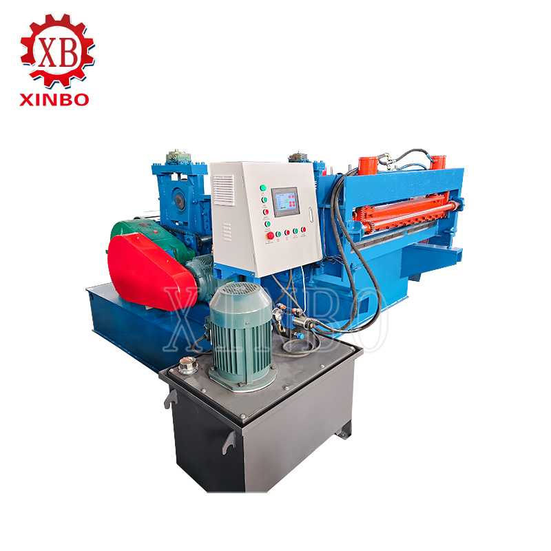
An uneven embossed pattern or distorted sheet is a symptom, not a diagnosis. Effective metal embossing machine troubleshooting starts by locating the defect across the width and feed direction. Then verify material, guides, roller gap and alignment, pressure, and downstream support before changing one setting at a time. This avoids masking a feed problem with extra pressure.
Map the Defect Before Adjusting the Machine
Stop and record the material batch, thickness, width, pattern, line speed, pressure or gap setting, and when the defect first appeared. Mark feed direction on samples. Compare the left, center, and right of the sheet, then compare the beginning, middle, and end of a run.
– A deeper pattern on one side suggests a widthwise gap, alignment, feeding, or loading imbalance.
– A pattern that fades or intensifies along the length suggests changing feed tension, material condition, pressure, or speed.
– Bow, camber, edge wave, center buckle, and twist point to different material-flow or handling conditions.
– Local scratches, dents, coating damage, or cracked areas require an inspection of contact surfaces and forming severity.
Use a repeatable inspection and an approved reference sample rather than judging depth from one photograph.
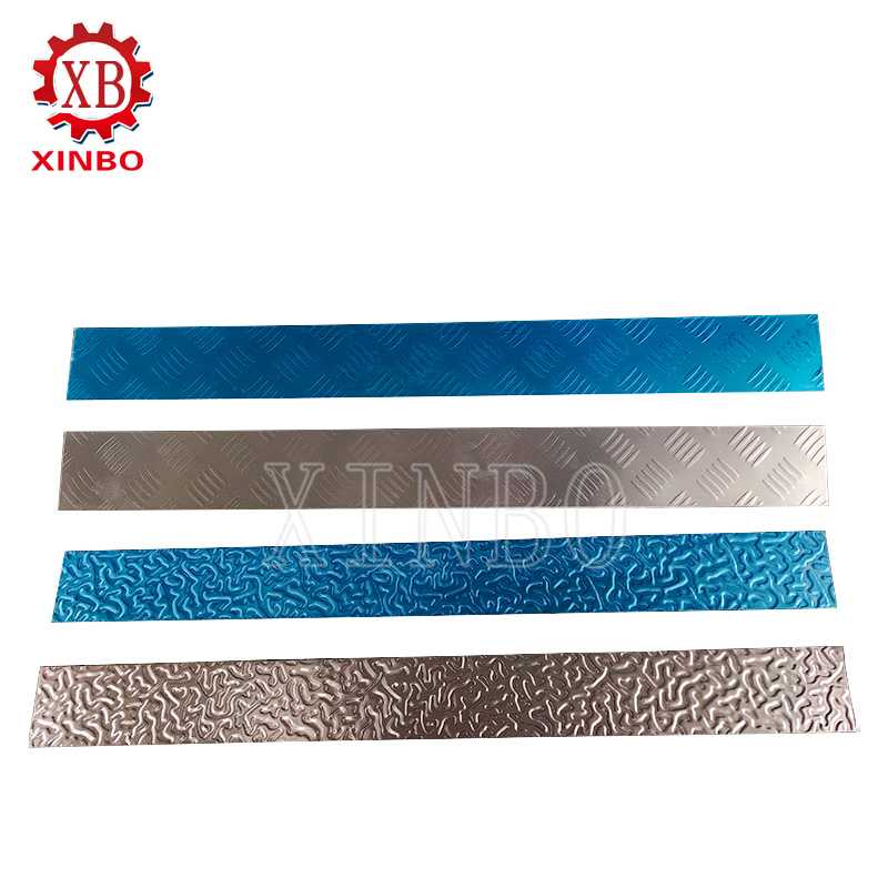
These strips illustrate pattern variation, not defects. Inspect against the ordered pattern.
Uneven Patterns Across the Sheet Width
Check roller parallelism and bearings
When one side is consistently deeper, first check whether the upper and lower embossing rollers are parallel and properly seated. Inspect bearing play, shaft condition, frame level, mounting surfaces, and loose fasteners. Contamination under a support can change the working gap even when the adjustment indicators appear equal.
Verify the gap at multiple points using the maker’s approved method. Record the original setting and check whether both sides respond consistently. Do not increase pressure to compensate for a skewed roller pair.
Verify centering and guide restraint
A strip that enters off-center can place an uneven load on the rollers. Check the actual sheet width, guide position, and whether one edge rubs or is forced inward. Guides should locate the material without buckling or marking it. If the defect shifts when the strip position changes, investigate feeding before reworking the engraving.
Inspect the pattern surfaces
Packed debris, a damaged engraving, burrs, or a mismatched upper and lower roller pair can produce local shallow or crushed areas. Clean according to the machine instructions, inspect the full circumference, and compare a new sample. If damage remains visible on the roller, stop rather than continuing to compensate with pressure.
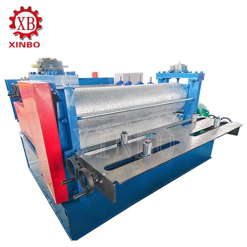
Patterns That Change Along the Feed Direction
If the first sheet is acceptable but later output changes, inspect what varies during the run. Measure incoming thickness and width at several points and confirm material grade, hardness, temper, coating, and surface condition. A new coil or supplier batch may require a fresh setup even if the nominal thickness is unchanged.
Check coil set, incoming waviness, uncoiler drag, leveling, and guide contact. Intermittent tension or an unstable strip path can change the way the sheet enters the nip. Compare line speed with the speed used to approve the original sample. Listen for vibration and inspect drive synchronization, lubrication, and hydraulic pressure if applicable to the installed machine.
Xinbo’s metal sheet embossing product description mentions CNC-machined high-hardness alloy-steel rollers and variable-frequency speed adjustment. Those features do not diagnose a specific fault by themselves. A useful service record connects the defect to the material, roller set, speed, gap or pressure, and guide settings in use.
If variation repeats at a regular interval, compare its pitch with roller rotation or repeated material features. If it follows a restart, check whether pressure and feed speed return to the approved state together.
Fixing Sheet Distortion Without Hiding the Cause
Bow and camber
A sheet that curves after embossing may have entered with coil set, received unequal force across its width, or lost support at the exit. Compare an unembossed blank with the finished sheet. Check roller parallelism, centering, and any upstream leveler or downstream support. Do not increase pressure to counter a feed or support problem.
Edge wave and center buckle
These defects indicate nonuniform material displacement or residual stress. Consider pattern depth, roller geometry, excessive reduction, incoming waviness, and the position of the pattern relative to unembossed margins. Reduce the severity of a trial setting only within the machine and product specification. If the pattern itself is too deep for the material, tooling or material selection may need review.
Twist or diagonal distortion
Twist may follow an angled entry, unequal guide force, skewed roller gap, or frame and shaft misalignment. Verify that the strip enters square to the roller centerline and is supported after the nip. A diagonal defect that changes with guide position points to a different correction than one tied to a damaged roller.
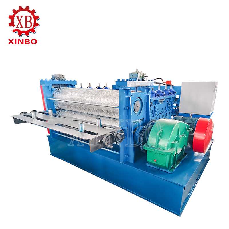
Use the equipment documentation for the actual adjustment procedure.
Use a Controlled Correction Sequence
Unrecorded changes make troubleshooting slower and can introduce a second defect. Apply a controlled sequence:
- Stop safely and isolate energy before inspection where required by the site procedure.
- Save the current setup, mark samples, and identify the material batch.
- Clean and inspect rollers, guides, bearings, fasteners, and the material path.
- Verify material thickness, width, hardness or temper, and surface condition.
- Check gap or pressure references and alignment across the full working width.
- Change one variable, run a short sample, and compare the same inspection points.
Keep the correction only when pattern consistency, flatness, surface quality, and dimensions improve together. If the machine shows abnormal noise, bearing play, unstable pressure, or damaged tooling, pause production and obtain qualified service support. Do not bypass guarding or adjust moving rollers by hand.
Verify the Fix on a Production Run
A good-looking short piece is not sufficient. Run representative material long enough to observe stability, then collect samples from the beginning, middle, and end. Inspect left, center, and right positions. Record pattern depth or visual grade, pitch, registration, flatness, bow, edge wave, twist, scratches, coating damage, and any downstream fit requirement.
Keep the accepted sample and setup record together. If the metal will be cut, bent, laminated, recoiled, or installed, verify the next operation too.

The installed ceiling illustrates why surface consistency can matter to the finished application. It does not establish that this particular installation used the machine pictured in the other images.
When to Escalate to Tooling or Supplier Review
Escalate if cleaning, material verification, centering, and alignment do not resolve the defect. Damaged engravings, unstable hydraulics, bearing play, shaft runout, or a frame that cannot maintain a parallel gap require review. Persistent distortion may call for revised tooling or upstream leveling.
إن آلة النقش is presented by Xinbo for customer-specified logos or patterns. A related metal sheet embossing machine page describes rollers and speed control for sheet applications. Confirm which configuration and tooling are installed before applying any machine-specific remedy.
For technical review, contact Xinbo’s team with marked samples, the pattern drawing, material specification, machine settings, defect photos, and the required output. These records are more useful than a description such as “the pattern is uneven.”
استنتاج
The reliable way to fix uneven patterns and sheet distortion is to classify the defect, compare it with incoming material, verify feed and alignment, inspect the rollers, and adjust one variable at a time. Confirm the result across the width and over a sustained run. Treat material, tooling, pressure, speed, and handling as one process rather than assuming a single setting will solve every symptom.
أسئلة متكررة
Why is one side of the pattern deeper?
Possible causes include roller misalignment, unequal gap or pressure, off-center feeding, bearing wear, or an angled sheet entry. Check centering and parallelism before adding pressure.
Why does the pattern become faint during production?
Material variation, unstable feed tension, hydraulic or drive instability, contamination, or a speed outside the approved setup range can change pattern transfer. Record when the change begins.
Can higher pressure fix a weak pattern?
Not necessarily. It may also thin or distort the sheet and overload components. Verify alignment, material, and roller condition first.
What proves that the correction worked?
Inspect marked samples across the width and through a representative run. Confirm pattern, flatness, surface condition, dimensions, and downstream suitability against the approved sample.
مشاركات ذات صلة
+


 Arabic
  English
  Spanish
  Portuguese
  Russian
  French
  Dutch
Dutch  Turkish
  Swahili
  Serbian
  Romanian