الإسبانية
 روسيا

Metal Stud Sizes and Gauge for Roll Forming Buyers
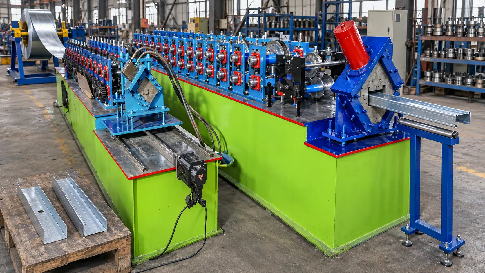
Metal stud size is not one number. A complete specification combines web depth, flange width, lip length, material thickness, coating, length, and any punchouts. Gauge is common jobsite language, but it can be ambiguous because equivalent and structural products may use different base metal thicknesses under a similar gauge label. A roll forming machine buyer should therefore request the actual drawing and thickness in millimeters or mils, not rely on gauge alone.
This guide translates metal stud dimensions into machine inputs. It explains which measurements define the C shaped stud, how track clearance changes the companion profile, and why tooling, punching, cutting, and quality checks depend on the full section rather than a catalog nickname. Project load capacity, maximum wall height, spacing, and code compliance remain engineering decisions and should be verified separately.
How to Read Metal Stud Dimensions
A metal stud drawing normally starts with the web, the broad center face that determines the nominal wall cavity depth. Each side then turns into a flange. The flange ends may turn again to form lips, which stiffen the open edges. Inside bend radii complete the geometry. The same nominal web depth can be combined with different flange, lip, radius, and thickness values, so a nominal size does not fully define the part.
|
Drawing field |
What it describes |
Why the machine buyer needs it |
|
Web depth |
Main section depth |
Controls central roll positions and nominal wall depth |
|
Flange width |
Side legs of the C section |
Changes forming passes, track fit, and screw surface |
|
Lip length |
Return at each flange edge |
Affects edge stiffness and final tooling geometry |
|
Inside radius |
Bend transition |
Influences tooling clearance and finished dimensions |
|
Base metal thickness |
Steel before coating |
Controls roll gap, forming load, springback, and cutting |
|
Punchout pattern |
Service or fastening openings |
Sets punch tooling, pitch, datum, and line timing |
Common Size Classes Are Only a Starting Point
North American product families commonly group studs by nominal web depths such as 1 5/8, 2 1/2, 3 5/8, 4, 6, and 8 inches, with additional structural depths available. Flange options and thicknesses vary by product family. The SSMA Product Technical Guide illustrates how manufacturer designations separate member depth, flange width, section style, and mil thickness. These conventions help decode a specification, but the approved project submittal remains the controlling source.
For machine procurement, build a size matrix rather than sending one sample. List the web range, every flange and lip combination, required thickness, material grade, coating, and finished length range. This reveals whether adjustable tooling can cover the family or whether dedicated cassettes, separate passes, or additional tooling will be required.
How to Use a Metal Stud Gauge Chart
Use a metal stud gauge chart only as a decoding aid. One mil equals 0.001 inch, or 0.0254 mm, so mil and millimeter values describe physical thickness directly. Gauge is a designation, not a universal conversion formula. Terms such as 20 gauge, 20 gauge equivalent, and structural 20 gauge are not interchangeable until the base metal thickness and applicable product specification are confirmed.
The RFQ should distinguish base metal thickness from coated thickness. It should also state the steel grade or minimum yield strength because two coils with the same thickness can form differently when their mechanical properties differ. Yield strength affects springback and the force needed at the rolls and cutoff. Coating type and surface condition can also affect feed behavior, marking, and tooling maintenance.
Stud and Track Must Be Specified Together
A stud fits inside a track, so the track cannot simply copy the stud web dimension. The track drawing needs its own inside width, flange height, thickness, radius, and clearance allowance. Too little clearance can make assembly difficult; too much can create unwanted movement before fastening. The correct relationship depends on the product system and tolerance stack.
Buyers considering a stud and track roll forming machine should provide both drawings and identify which profiles share material and production schedules. Xinbo lists a processing thickness of 0.8 to 1.2 mm for the referenced model, with 13 forming rollers, hydraulic profile cutting, encoder length measurement, PLC control, and a published speed range of 0 to 15 m/min. Those values apply to the listed configuration and should be checked against the required size matrix.
How Metal Stud Dimensions Affect the Roll Forming Line
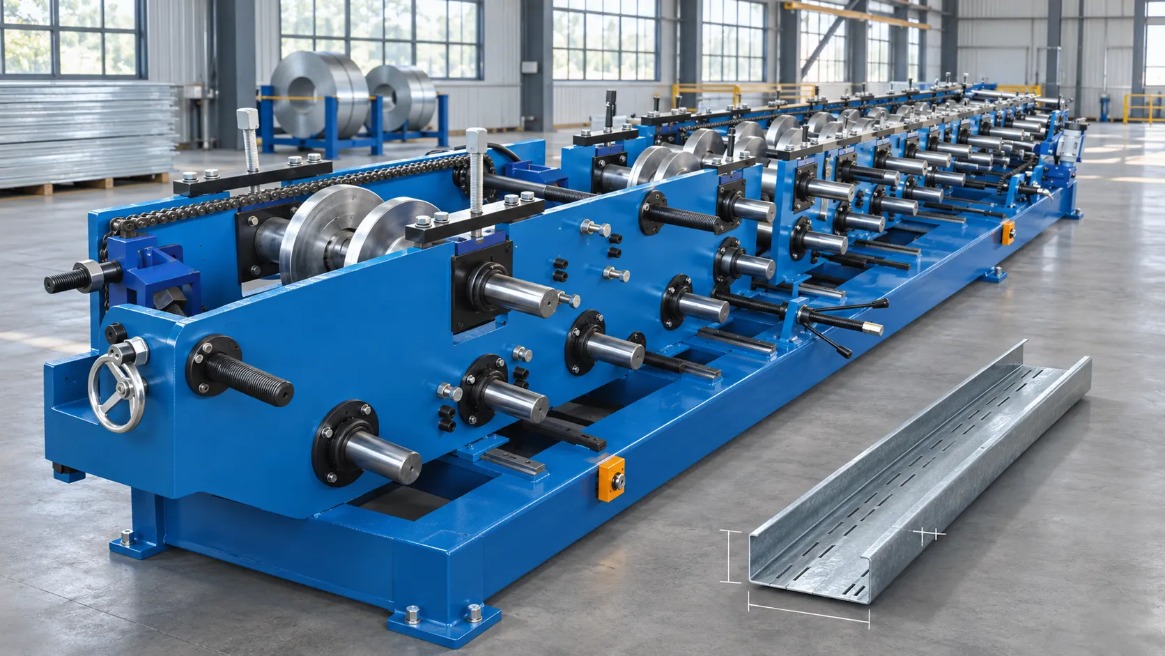
Every section dimension changes the forming task. Web adjustment moves the side forming groups. Flange and lip changes affect the later passes, where the section is more enclosed and interference risk is higher. Thickness and yield strength influence roll gap, springback, drive load, straightness, and cutoff behavior. Punchout size and pitch affect the feed and control cycle, especially when holes must maintain a fixed relationship to the cut ends.
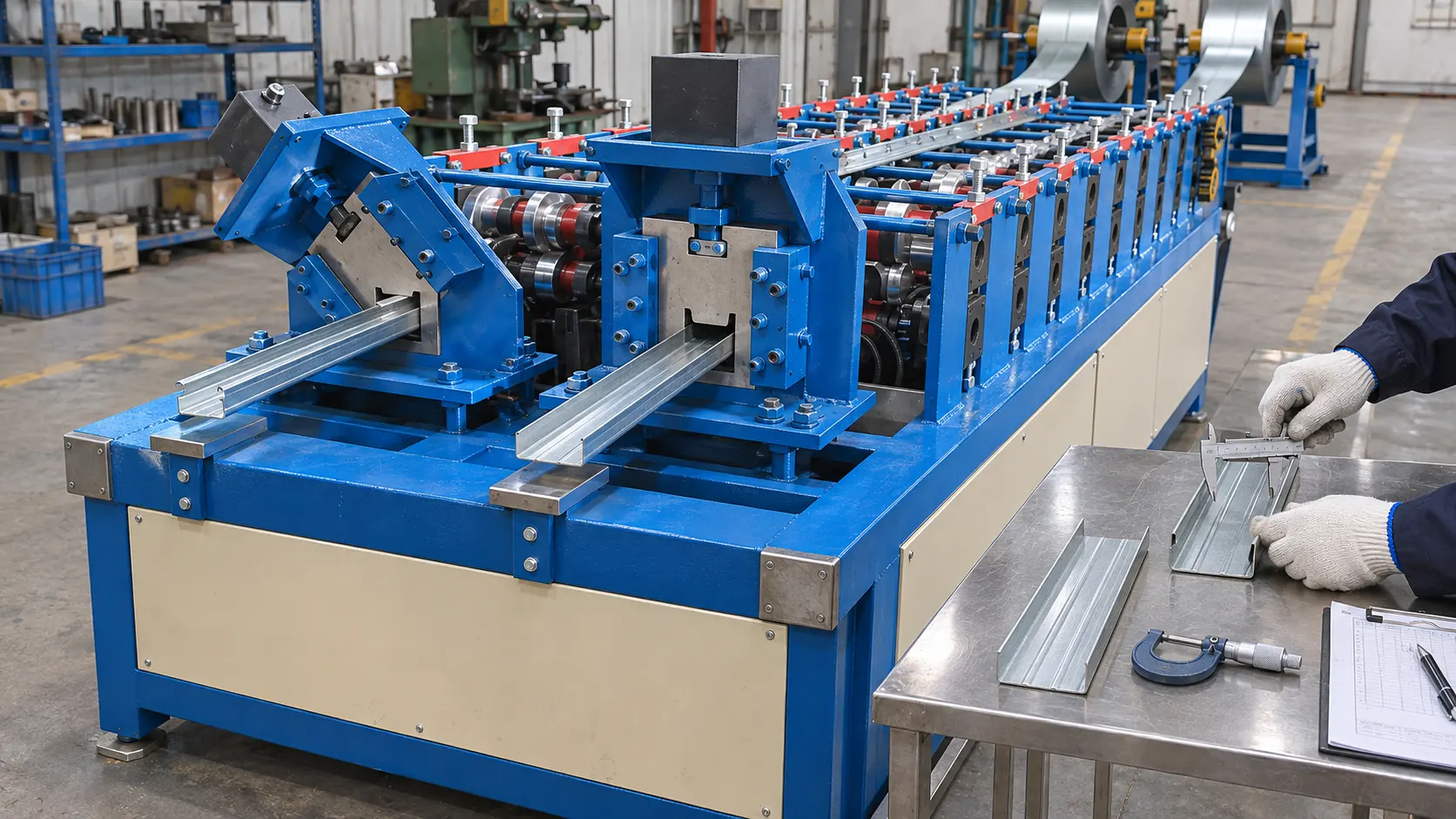
A supplier should review the complete profile envelope before confirming automatic adjustment. Ask which dimensions change from the control screen, which require manual spacers or tooling changes, and which profiles need a separate roll set. If two studs share a web depth but use different flanges or lips, the changeover may be more involved than the size label suggests.
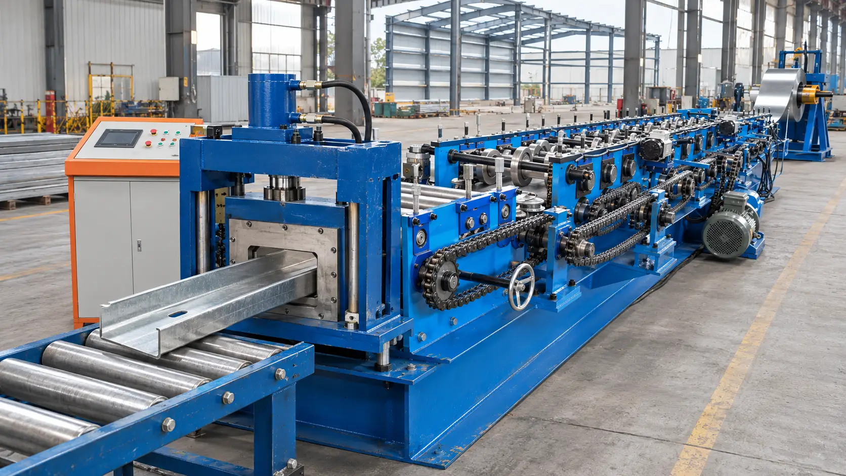
إن dual running C/U channel roll forming process provides useful background on decoiling, feeding, progressive forming, cutting, and control. For a purchasing decision, however, the key evidence is a trial made from the buyer’s specified material and drawings, followed by measurement of the finished sections.
Quality Checks for a Size Change
After any size or thickness change, inspect a first piece before releasing continuous production. Measure the web, both flanges, both lips, overall length, hole size, hole position, twist, bow, and end deformation. Check the stud against its track rather than inspecting the two profiles independently. A go or no go assembly fixture can reveal cumulative tolerance problems quickly.
Measurement methods should be agreed before the factory acceptance test. The drawing should state whether dimensions are outside, inside, or theoretical centerline values and whether coating thickness is included. A shared inspection sheet prevents a machine supplier and buyer from using different definitions for the same dimension.
Machine Specification Checklist
Use the stud and track machine range to identify the appropriate equipment family, then issue one controlled RFQ package containing:
- Dimensioned stud and track drawings for every required profile, including radii and tolerances.
- Material grade, minimum yield strength, coating, and base metal thickness range.
- Coil width or confirmation that the supplier will calculate strip width from the approved profile.
- Punchout shape, size, pitch, edge distance, and datum from the cut end or another defined reference.
- Length range, cut tolerance, target speed, batch sizes, and expected changeover time.
- Electrical standard, decoiler capacity, receiving method, and factory acceptance test parts.
Do not approve a line only from a generic video or one standard profile. The acceptance run should include the smallest and largest sections, minimum and maximum thicknesses, and at least one profile with the most demanding punch pattern. This verifies the real operating envelope rather than a convenient demonstration condition.
استنتاج
Metal stud sizes combine geometry and material. Web, flange, lip, radius, thickness, grade, coating, length, and punchouts all affect both finished framing and the roll forming line. Gauge alone is not a sufficient purchasing input. A controlled size matrix, paired stud and track drawings, and agreed inspection method give the machine supplier enough information to confirm tooling, adjustment, punching, cutting, and acceptance testing.
Frequently Asked Questions
Is gauge the same as metal thickness
No. Gauge is a designation and can be ambiguous. Specify the required base metal thickness in mils or millimeters and include the governing product specification.
What dimension defines a metal stud size
The nominal size usually refers to web depth, but a complete profile also needs flange width, lip length, bend radius, thickness, and tolerances.
Can one line make both studs and tracks
It may, depending on profile geometry, size range, thickness, tooling design, and required changeover method. Both drawings must be reviewed before capability is confirmed.
What should be tested during factory acceptance
Test the operating extremes, demanding punch patterns, cut length accuracy, profile dimensions, twist, bow, end condition, and stud to track fit using the agreed material.
To confirm whether a size family fits Xinbo’s published configuration, request a profile and thickness review and provide the stud and track drawings, material data, thickness range, punchout plan, and target output.
مشاركات ذات صلة
+


 Arabic
 English
 Spanish
 Portuguese
 Russian
 French
 Dutch
 Turkish
 Swahili
 Serbian
 Romanian