Kihispania
 Urusi
Urusi
Retractable Banner Stand Top Bar Roll Forming Machine: A Guide to Custom Profile Tooling
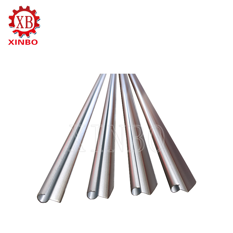
A retractable banner stand top bar looks simple, but its clamping lip, slot geometry, straightness, surface condition, and cut length determine how securely a printed graphic fits. A retractable banner stand top bar roll forming machine must therefore be specified around the finished cross-section and the aluminum strip, not a generic machine speed. This guide explains how to define custom profile tooling, review the forming sequence, and approve a line before production.
Why a Top Bar Needs Profile-Specific Tooling
The top bar secures the graphic at the upper edge of a pull-up display. The visible face should remain presentable, while the functional edge must grip or retain the graphic as intended by the banner assembly. A small change in a lip, opening, or return can affect insertion, retention, end-cap fit, or the way the banner hangs. The exact geometry varies by stand design.
Roll forming builds the section through successive roller passes. For a narrow aluminum profile, forcing a difficult lip into shape too abruptly can lead to edge wave, twist, springback, or roller marks. The tooling designer should decide where each bend begins, how the material is supported, and which surfaces may contact the rollers.
The photograph above illustrates the top bar in a finished display; it is not a dimensional reference for a particular customer profile. Approve the actual machine against the buyer’s drawing and mating components.
Define the Profile and Material Before Designing Rollers
The first technical package should include a dimensioned cross-section, a physical sample if available, and the production material specification. Mark the critical opening, clamping surfaces, bend radii, visible face, allowable marks, and any end-cap or connector interfaces. Identify which dimensions affect assembly and which are cosmetic.
Specify the aluminum grade or alloy, temper, thickness range, coating or anodized finish, strip width, width tolerance, and coil dimensions. These details affect springback, surface sensitivity, and the roller load. If the material or drawing is provisional, treat the tooling proposal as conditional until a representative sample is tested.
Also define finished lengths, cut-length tolerance, output quantity, batch size, and how often the profile changes. A single high-volume section and a family of short-run sections may need different tooling and changeover strategies. State whether the machine is expected to count, collect, or protect bars after cutting.
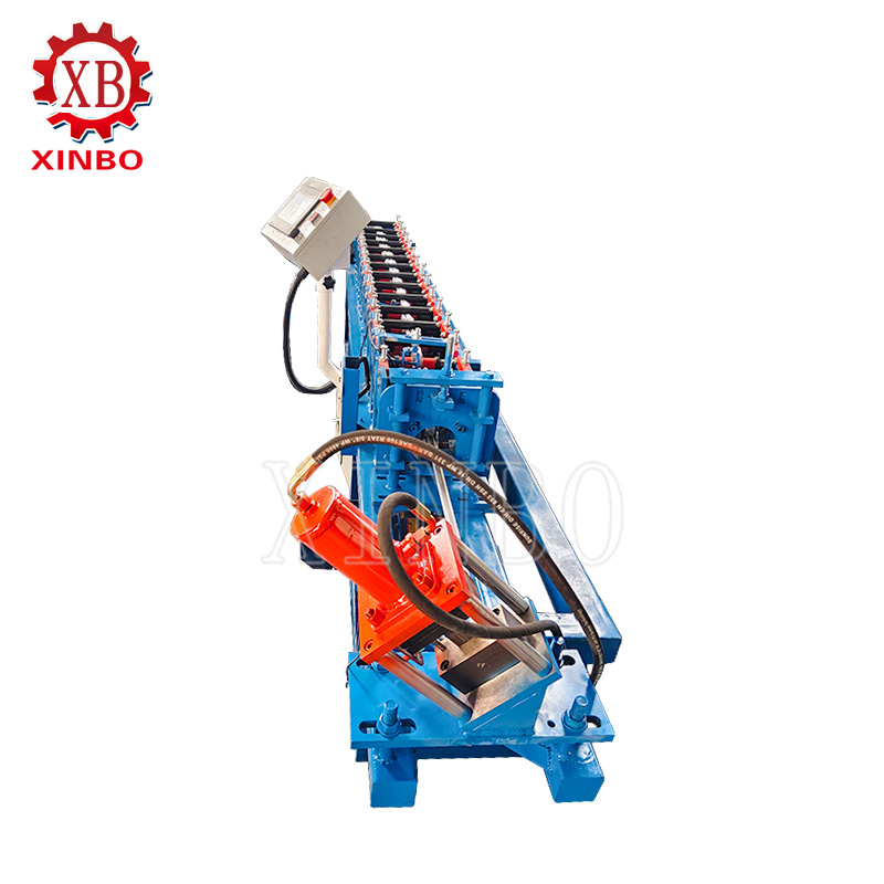
Xinbo’s product description identifies an adjustable input section for different strip widths, a forming section for customer profiles, and PLC-controlled cutting to specified lengths. The actual adjustment range and tolerance must be agreed for each project.
Build a Forming Sequence Around the Critical Features
Start with the cross-section
The tooling designer should translate the approved section into a sequence of forming passes. Ask which pass establishes each lip, slot, and return, and where the strip is supported before the next bend. A pass design should avoid concentrating deformation in one station simply to reduce the number of rollers.
For a profile with a tight clamping feature, the most important question is not only whether the final outline can be formed. It is whether the functional opening remains consistent along the bar without squeezing the strip, scratching the visible face, or leaving a springback error after cutting.
Protect the visible surface
Tooling finish and cleanliness matter as much as nominal geometry. Burrs, chips, rough guides, or excessive lateral restraint can mark aluminum. Define which side faces the customer, whether protective film is used, and how the strip will pass through guides and the cutter. Inspect trial bars under the agreed lighting and handling conditions.
Plan changeovers realistically
Several related top-bar sections might use interchangeable roller sets or adjustable tooling, but a machine is not automatically universal. Compare the profile differences, change frequency, roller weight, adjustment references, storage, and the first-piece inspection required after each change. A documented setup recipe helps operators return to an approved configuration.
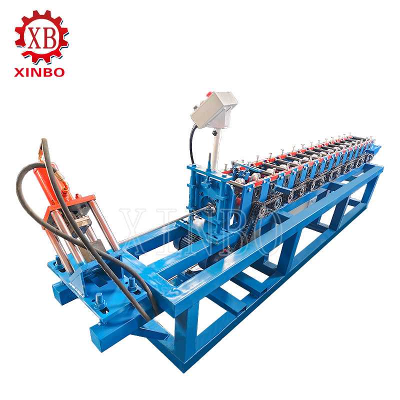
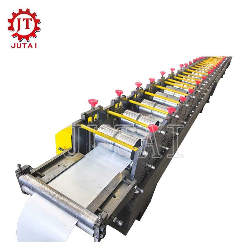
The machine photo shows successive forming stations. Their exact number and tooling geometry depend on the approved profile rather than the appearance of a catalog image.
Specify the Complete Machine, Not Just the Roller Set
Good rollers cannot compensate for unstable feeding or an uncontrolled cut. Review the line as a connected process:
– Entry and guides: Confirm the strip-width range, centering method, setup reference, and surface protection.
– Forming stations: Request the pass layout, roller identification, adjustment points, and maintenance access.
– Cutting: Define the length-setting method, measurement reference, end quality, tolerance, and restart behavior.
– Controls: Confirm recipes, alarms, counting, emergency stops, and operator access appropriate to the proposed configuration.
– Collection: Support the full bar length and prevent finished surfaces from rubbing during transfer and packing.
Xinbo states that its line uses PLC control for customizable cut lengths. That does not establish a universal accuracy figure. The buyer should agree on the cut-length tolerance, material, test speed, sample quantity, and inspection method in the technical agreement.
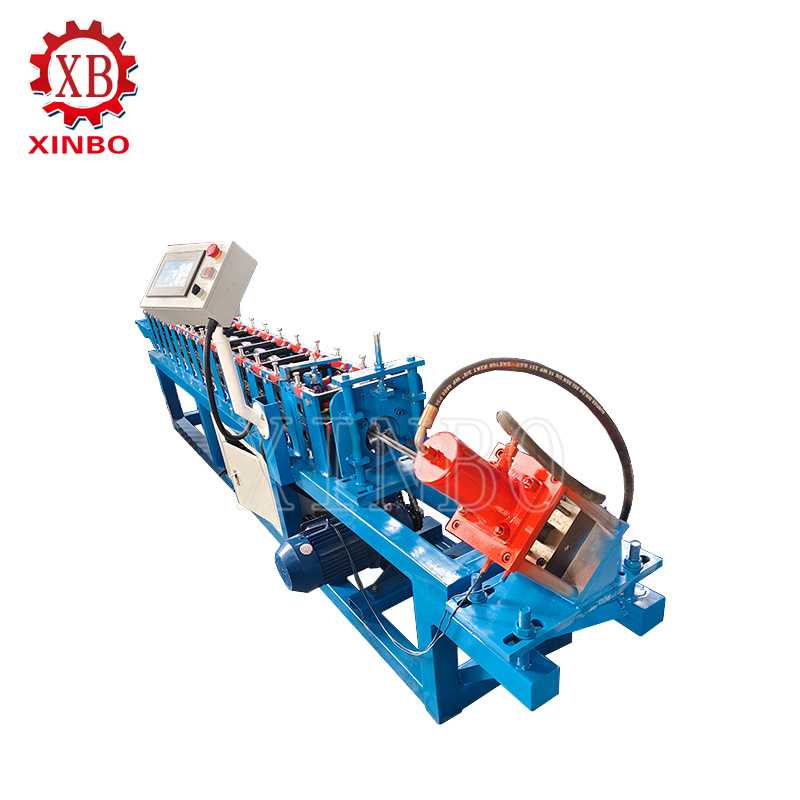
The proposed line must also fit the workshop’s power supply, floor space, coil handling, operator arrangement, and downstream assembly. Clarify which equipment is included in the quote and which interfaces the buyer must provide.
Approve the Tooling with a Representative Trial
The drawing review is only one gate. Run the intended aluminum, then inspect samples from the beginning, middle, and end of a sustained test. Check the critical dimensions with the same measurement method that will be used in production. Test the top bar with the actual graphic and mating components where practical.
The acceptance record should cover profile dimensions, clamping fit, straightness, bow, twist, edge condition, visible-surface marks, cut length, cut-end quality, and behavior after a stop and restart. If multiple sections are part of the purchase, repeat the check after a changeover. Record the material batch and machine settings so the approved sample can serve as a future reference.
If a sample misses the agreed criteria, distinguish tooling geometry from feed alignment, material variation, and cutting setup before changing the rollers. Agree in advance how corrections and repeat tests will be handled. A physical pass/fail sample is more useful than a broad promise of precision.
What to Include in a Custom Tooling RFQ
Send the supplier the profile drawing or sample, aluminum specification, strip-width and thickness ranges, finish requirements, finished lengths, target quantity, product mix, and workshop constraints. Identify critical dimensions and the mating banner components. Ask for the roller/tooling scope, line layout, controls, utilities, spare parts, acceptance test, and supply boundary.
Xinbo presents custom design support for customer profiles and describes inspection before shipment. For this machine, every profile, tooling set, acceptance criterion, document, and service obligation still needs written confirmation. Compare quotations by the usable part they must produce, not just maximum speed.
For a profile-specific review, share the drawing, material data, target length, production mix, and acceptance sample. Xinbo’s Retractable Banner Stand Top Bar Roll Forming Machine page provides the machine context; contact the technical team to confirm the configuration.
Hitimisho
Custom profile tooling is the foundation of a stable banner top-bar line. Define the section and material first, form critical features progressively, protect the visible face, and validate the result on representative aluminum. Evaluate feeding, forming, cutting, changeover, collection, and acceptance evidence together. The final configuration must match the buyer’s drawing and sample rather than a generic machine description.
Maswali ya kawaida
Can one line produce several top-bar profiles?
Possibly, if its structure and tooling strategy support the intended profile family. Confirm roller sets, changeover steps, alignment references, and acceptance checks for every section.
What information matters most for custom tooling?
Provide the profile drawing, aluminum grade and temper, thickness, strip width, visible-surface requirement, finished length, tolerance, and mating components.
How can roller marks be reduced?
Identify the visible face, keep rollers and guides clean, control contact and alignment, and inspect a representative production run. The appropriate method depends on the finish.
Posts kuhusiana

Ubora mzuri
XinBo mashine kufanya CO. LTD ni mtengenezaji wa kitaalamu na nje katika roll kuunda mashine,
Tazama zaidi→


 Swahili
  English
  Spanish
  Portuguese
  Arabic
  Russian
  French
  Dutch
Dutch  Turkish
  Serbian
  Romanian